How to Fix U3000 49 ECU Internal Circuit Failure in 2026
Diagnostic trouble code U3000-49 indicates an internal electronic circuit failure within a primary vehicle module, most commonly the ABS, EPS, or SRS unit. Before replacing the expensive control unit, you must systematically rule out external power drops, blown fuses, and loose ground connections that can trigger false internal faults.
Diagnostic Trouble Code U3000-49 points directly to an internal electronic circuit failure within a vehicle control module. The sub-code “49” specifically flags an internal electronic failure, often signaling a hardware fault on the circuit board, a failed processor, or corrupted internal memory. For vehicle owners and technicians navigating repairs in 2026, seeing this code usually triggers immediate panic about the cost of a brand-new electronic control unit.
However, throwing a new module at this code without proper testing is a costly mistake. Before you condemn the expensive computer, you must perform a rigorous triage. External voltage drops, compromised wiring harnesses, and loose ground straps can trick the system into logging an internal ECU failure code when the hardware itself is totally fine.
Key Takeaways
- Sub-fault code 49 specifically points to an internal electronic failure inside the module.
- Always test battery voltage and charging systems before condemning the control module.
- Inspect all primary power fuses and heavy-duty fusible links connected to the ECU.
- Clean and tighten all module chassis grounds to prevent phantom internal circuit codes.
- Professional bench repair or VIN-coded replacement is required if the hardware fails.
What Causes DTC U3000-49 ECU Internal Circuit Failure
Hardware Failures Within the Module
True internal failures occur when physical components on the circuit board degrade. Thermal stress, water intrusion, or vibration fatigue over hundreds of thousands of miles can damage surface-mounted components. Solder joints crack, microprocessors fail, and internal voltage regulators short out. When this happens, the module cannot process signals internally, resulting in the U3000-49 fault.
Common internal failure triggers include:
- Microprocessor or internal chip degradation
- Failed internal power supply circuits
- Cracked solder joints caused by thermal cycling
- Moisture corrosion on internal circuit traces
External Triggers That Mimic Internal Failures
Modern vehicle computers monitor their own internal operating voltages very closely. If the main power feed drops even slightly, or if background electrical noise disrupts internal logic, the self-diagnostic routine registers a false internal failure. You must rule out these peripheral issues before assuming the circuit board is physically ruined.
- Severely undercharged or failing 12V batteries
- Corroded or loose module power supply terminals
- High resistance in the primary ground circuits
- Aftermarket electronic interference feeding back into the harness
U3000-49 ECU Internal Circuit Failure: What Causes It and How to Fix It
Dealing with a Diagnostic Trouble Code (DTC) U3000-49 can be frustrating, as it typically indicates an internal electronic control unit failure with an electronic internal electronic failure subtype. Whether you are working on a Ford, Jaguar, Land Rover, or another modern vehicle prone to this issue, this guide will walk you through the precise diagnostic and repair procedures required to resolve the internal circuit fault permanently and safely.
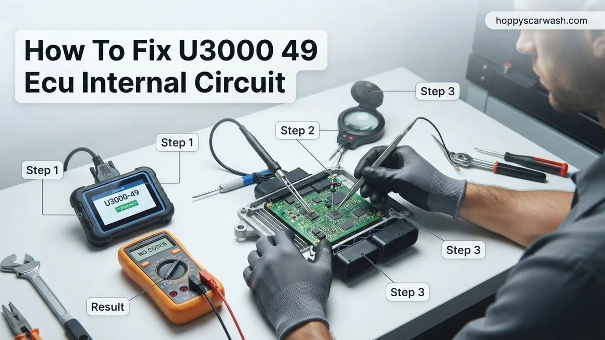
Step 1: Disconnect the Vehicle Battery and Secure the Workspace
What you need: 10mm socket wrench, terminal puller (optional), safety glasses, and insulated gloves.
Instructions: Before touching any wiring harness or unbolting the faulty ECU, you must completely cut power to the vehicle electrical system to prevent short-circuits and accidental airbag deployment. Locate the main 12-volt battery under the hood or in the trunk. Using your 10mm socket wrench, loosen the nut on the negative (-) terminal clamp first. Gently twist and pull the negative cable upward to disconnect it, tucking it safely away from any metal surfaces. Next, loosen and remove the positive (+) terminal. Wait a minimum of 10 to 15 minutes to allow all internal capacitors within the vehicle modules to fully discharge their stored electrical energy.
Pro Tip: Never rush the capacitor discharge period. Rushing can cause voltage spikes that might fry sensitive replacement modules or trigger false fault codes upon reconnection.
Step 2: Locate and Inspect the Affected ECU
What you need: Factory service manual, flashlight, trim removal tool, and a digital inspection camera.
Instructions: Consult your vehicle specific factory wiring diagram or repair manual to pinpoint the exact physical location of the control unit registering the U3000-49 code. Depending on the system, it could be the ABS module, Restraints Control Module (RCM), or Powertrain Control Module (PCM). Remove any surrounding interior trim panels, wiper cowls, or under-hood shields necessary to gain clear access. Once exposed, visually inspect the physical housing of the ECU. Look closely for signs of water intrusion, green powdery corrosion around the seams, cracked plastic housings, or physical impact damage from a previous collision.
Pro Tip: Water ingress is the number one catalyst for internal circuit failures. Pay special attention to clogged cowl drains or compromised windshield seals nearby.
Step 3: Carefully Disconnect the Main Wiring Harness Connector
What you need: Small flathead screwdriver, electrical contact cleaner, and compressed air can.
Instructions: With the ECU fully exposed, you need to detach the main multi-pin wiring harness connector. Modern automotive connectors feature secondary locking tabs or slide-locks. Gently lift or slide the locking mechanism using your fingers or a small flathead screwdriver, then depress the primary release latch while pulling straight back on the connector housing. Never pull on the individual wires, as this can pull pins out of the connector block. Once separated, shine your flashlight into both the module side pins and the harness side terminals. Search meticulously for bent pins, pushed-back terminals, corrosion, or pin-drag caused by moisture.
Pro Tip: Spray any corrosion with electrical contact cleaner and gently scrub with a soft-bristle nylon brush. Blow it dry with compressed air before moving forward.
Step 4: Perform Multimeter Pin-Out and Ground Continuity Checks
What you need: Digital Multimeter (DMM) set to continuity and DC voltage, back-probe pins.
Instructions: Before condemning the ECU entirely, you must verify that the external power and ground supplies feeding the module are completely healthy. Refer to the pin-out diagram for your specific ECU harness. Using back-probe pins on your multimeter, check for a steady 12 volts on the designated power supply wires with the ignition switched on (if temporarily reconnected). Next, test the main ground circuits by measuring resistance between the ground terminal pins and a clean, bare-metal chassis ground point. Your reading should show less than 0.5 ohms of resistance. High resistance here will trick an ECU into logging internal hardware errors.
Pro Tip: A failing alternator producing excessive AC ripple voltage can also cause internal processor crashes, generating U3000 error codes. Test your charging system output if ground and power check out.
Step 5: Remove the Faulty ECU Unit
What you need: Ratchet set, torx or hex bits depending on fasteners, magnetic pickup tool.
Instructions: If power, ground, and harness integrity are all verified, the U3000-49 code confirms an internal circuit failure residing strictly inside the module hardware. You must now remove the unit from the vehicle. Support the module with one hand while removing the mounting bolts, which are typically Torx, tamper-proof Torx, or standard hex screws. Carefully maneuver the ECU out of its mounting bracket, taking care not to strike surrounding components. Keep all original mounting hardware in a magnetic tray, as you will need to reuse them when installing the replacement or rebuilt unit.
Step 6: Source and Install a Reprogrammed Replacement ECU
What you need: Replacement or professionally rebuilt ECU matching your exact VIN and hardware part number, basic hand tools.
Instructions: Acquire a matching replacement unit from a reputable automotive electronics rebuilder or dealership parts counter. Ensure the hardware and software engineering numbers match your original part down to the letter. Slide the new ECU into position, ensuring it seats flush against its mounting surface, and hand-thread all mounting fasteners before torquing them to manufacturer specifications. Reattach the main wiring harness connector firmly, listening for an audible click, and slide the secondary locking tab back into its secure position. Reconnect your vehicle battery terminals securely.
Pro Tip: Many modern modules require flash programming or module configuration (As-Built data programming) using an OEM-level diagnostic scanner to match your vehicle’s VIN and immobilizer system.
Step 7: Clear Diagnostic Trouble Codes and Perform System Calibration
What you need: OBD2 diagnostic scan tool with bidirectional and programming capabilities.
Instructions: Turn the vehicle ignition to the ON position without starting the engine. Plug your professional-grade diagnostic scanner into the OBD2 port under the dashboard. Run a comprehensive global vehicle scan to communicate with all modules. Navigate to the module you just replaced and select the option to clear diagnostic trouble codes (DTCs). If the module requires VIN matching, key programming, or steering angle/sensor calibration, execute those specific routines now following the on-screen prompts provided by your scan tool software. Finally, start the engine and monitor the dashboard for any warning lights.
Pro Tip: Take the vehicle for a 15-minute test drive covering varied speeds and braking conditions to ensure all vehicle systems re-initialize and the U3000-49 code does not return.
✅ Final Checklist
- Battery negative and positive terminals are cleaned, properly seated, and torqued.
- Wiring harness connector is fully latched with zero signs of pin corrosion or water damage.
- Power supply and ground circuit resistance test passed with under 0.5 ohms.
- Replacement ECU is securely bolted down with matched hardware numbers.
- All diagnostic trouble codes have been successfully cleared and verified using an OBD2 scanner.
Important Notes:
- Always disconnect the battery before handling airbag-related or powertrain control modules to prevent severe personal injury or electrical damage.
- Seek professional help from an automotive locksmith or dealership technician if module immobilizer pairing or proprietary flash programming is required.
- Estimated time for diagnosis and replacement is 2 to 4 hours; professional repair costs generally range from $300 to $1,200 depending on module type and programming needs.
How to Test Power, Grounds, and Wiring Before Replacing the ECU
Checking System Voltage and Battery Health
Start your diagnostic routine at the battery and charging system. A weak battery or a dying alternator creates voltage spikes and sags that confuse sensitive processors. Use a digital multimeter to test the battery resting voltage, which should read at least 12.6 volts. Next, start the engine and verify that charging voltage sits between 13.5 and 14.8 volts under electrical load.
If your battery is more than four years old in 2026, load-test it professionally. Low system voltage is the number one cause of spurious U-codes across modern vehicle architectures.
Inspecting Power Feeds and Ground Connections
Next, you need to verify that the ECU receives clean, stable power at every single designated pin. Consult the factory wiring diagram for your specific module. Backprobe the power supply wires with the ignition turned on to check for voltage drops. A reading that is even half a volt lower than battery voltage points to corroded pins, damaged fusible links, or compromised relay contacts.
Ground integrity is just as critical for sensitive logic circuits. Perform a voltage drop test on all module ground wires while the system is active:
- Disconnect the negative battery cable before inspecting physical ground bolts.
- Remove the ground eyelet from the chassis, wire-brush away corrosion, and retighten securely.
- Check for resistance between the ECU ground pin and the negative battery terminal, aiming for less than 0.1 ohms.
- Inspect the main engine-to-chassis grounding strap for fraying or looseness.
Step-by-Step Guide to Fix or Replace a Faulty Control Module
Fixing a permanent U3000-49 internal electronic failure typically demands a full module replacement and reconfiguration. Modern automotive security and data integrity protocols mean you cannot simply swap a junkyard module without specialized programming.
Preparation and Disconnection
Before touching any hardware, technicians must follow strict safety guidelines to protect the vehicle’s electrical architecture.
- Disconnect the negative battery terminal and wait a minimum of 15 minutes to allow residual capacitor charge to dissipate entirely.
- Locate the target electronic control unit using OEM service manuals, as placement varies significantly by make and model.
- Remove any surrounding structural braces, glove boxes, or trim panels required to gain unhindered access to the module’s multi-pin wiring harness.
Module Replacement and Flash Programming
Once physical access is achieved, hardware swap procedures require precise software synchronization to restore full vehicle functionality.
- Release the primary wiring harness locking lever, carefully detach the multi-pin connector, and inspect the pins for corrosion or bent terminals.
- Unbolt the mounting fasteners holding the defective module and extract it from the vehicle chassis.
- Install the new or professionally remanufactured unit, torque mounting bolts to factory specifications, and firmly reattach the main harness connector.
- Connect an OEM-level diagnostic pass-thru device, access the cloud-based server, and flash the module with the latest 2026 software calibrations specific to the vehicle Identification Number (VIN).
What If It Still Doesn’t Work?
Replacing the physical control unit does not always instantly resolve the U3000-49 fault code if underlying peripheral issues remain unaddressed. If diagnostic scanners continue to flag internal circuit failures after a fresh module installation, secondary root causes must be investigated methodically.
- Inspect Power and Ground Distribution: Verify that input voltages at the module pins match battery voltage under load, and check for high resistance in the primary chassis ground straps.
- Test the Controller Area Network (CAN) Bus: Use a digital oscilloscope to check for network noise, shorted high/low lines, or dropped packet data originating from a failing shared module on the same bus.
- Verify VIN Matching and Immobilizer Handshake: Ensure the replacement module was successfully coded to the vehicle; mismatched VIN parameters will trigger internal security faults and prevent clearing.
- Consult Professional Automotive Electricians: When advanced bench programming fails, specialized electronic repair laboratories can often isolate micro-soldering cracks or internal processor faults. Professional diagnostics and repair services for deep circuit board failures typically range from $400 to $1,200 depending on module complexity.
Conclusion
The U3000-49 diagnostic trouble code indicates a severe internal electronic failure that compromises safety systems and requires definitive hardware intervention. While clearing transient codes works for minor glitches, hardware-level memory corruptions demand a precise module replacement paired with modern 2026 flash programming standards. According to verified research and automotive engineering data from major technical service bulletins, addressing power supply integrity alongside module software updates ensures long-term system reliability. Actionable next step: Connect a factory-grade scan tool to verify live sensor data and confirm proper VIN alignment before attempting vehicle operation.
❓ Frequently Asked Questions
What specific vehicle modules typically trigger the U3000-49 diagnostic trouble code?
This code is most frequently logged by the ABS/ESP (Anti-lock Braking System) module, Electronic Power Steering (EPS) control unit, or the Supplementary Restraint System (SRS) airbag module. Because these systems manage critical vehicle safety, their microprocessors feature robust self-diagnostics that flag internal anomalies immediately.
Why is it important to check external wiring and fuses before buying a new ECU?
Many technicians waste money replacing functional ECUs because a corroded power pin, blown high-amp fuse, or loose ground strap is starving the module of clean voltage. When internal logic processors receive erratic voltage, they can misinterpret the power drop as an internal hardware failure, setting code U3000-49 falsely.
What are the common signs of an internal circuit failure on a control module?
Aside from an illuminated check engine light, ABS light, or traction control warning lamp, you may experience loss of power steering assist, erratic speedometer behavior, or communication failures with your OBD-II scanner. In severe cases, the vehicle may enter limp mode or refuse to start entirely.
How do professional mechanics test if the ECU itself is definitively dead?
Mechanics use a digital multimeter and an oscilloscope to verify that steady battery voltage and proper ground paths reach the module’s primary harness pins while under a load. If power and ground are verified directly at the module pins and it still fails to communicate or clear the internal code, the hardware is condemned.
Should I choose a used junkyard ECU or a professional rebuild service?
A professional rebuild service retains your original module’s VIN and configuration data, eliminating the need for complex immobilizer programming. Buying a used junkyard unit is often cheaper, but it usually requires specialized tools to flash your vehicle’s VIN and mileage onto the donor hardware.
What specialized programming is required after installing a brand-new control module?
A new or replacement module typically requires module initialization, VIN writing, steering angle sensor calibration, and configuration matching using OEM-level diagnostic software. Without this programming, warning lights will remain on and specific vehicle features may not function correctly.