How to Test Mass Air Flow Sensor with Multimeter 2026
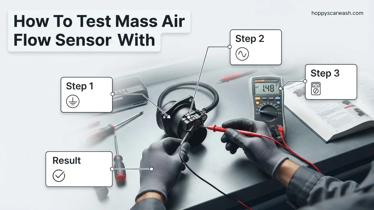
Testing a Mass Air Flow (MAF) sensor requires a digital multimeter to verify power supply, ground continuity, and signal voltage scaling. Back-probing the signal wire at idle and while revving the engine is the most effective way to identify a failing sensor causing engine hesitation or poor fuel economy.
Testing a Mass Air Flow (MAF) sensor with a digital multimeter requires back-probing the electrical connector while the engine is running to verify power supply, ground integrity, and signal voltage scaling. You will need a digital multimeter capable of reading DC volts with high precision, along with back-probe pins to safely pierce wire insulation or slide into the back of the wiring harness connector without damaging the weather seals.
Modern vehicle diagnostics in 2026 rely heavily on precise electrical testing to avoid costly, unnecessary part replacements. When your MAF sensor fails, your engine control unit (ECU) receives incorrect air density data, resulting in rough idling, poor fuel economy, hesitation during acceleration, and persistent check engine codes like P0101. Pinpointing the exact electrical fault takes less than fifteen minutes with a multimeter.
Key Takeaways
- Set your digital multimeter to DC Volts to measure sensor power and signal output.
- Always back-probe wires with the ignition on or the engine running without piercing insulation.
- A normal MAF signal reads around 0.5V to 1.0V at idle.
- Signal voltage should smoothly scale up to 2.0V–3.0V+ when accelerating the engine.
- A dirty MAF sensor can mimic failure, so clean it with specialized MAF cleaner before replacement.
What Causes Mass Air Flow Sensor Failure and Faulty Readings
Mass Air Flow sensors fail due to contamination, physical vibration, or internal electrical degradation over time. Understanding what goes wrong helps you determine whether your sensor actually needs replacement or just a simple cleaning.
Contamination and Debris Buildup
The tiny platinum heating wire or film inside your MAF sensor sits directly in the intake airstream. Over time, microscopic dirt particles, oil from aftermarket oiled air filters, and crankcase vapors coat the sensing element. This insulation layer prevents the sensor from accurately measuring the cooling effect of incoming air, leading to skewed voltage signals.
Internal Electrical and Circuit Failures
Constant engine vibrations and extreme under-hood temperature fluctuations stress the internal microchip circuitry and soldered electrical connections. Vibration can crack internal circuit board traces, causing intermittent signal dropouts. Additionally, water intrusion or corrosion in the main harness connector can degrade the reference ground or power supply voltage.
Master Mass Air Flow Sensor Testing in 8 Simple Steps
The Mass Air Flow (MAF) sensor is a critical component of your vehicle’s engine management system, responsible for measuring the volume and density of air entering the engine so the computer can deliver the precise amount of fuel. When this sensor fails or gets dirty, you might experience rough idling, engine stalling, poor acceleration, and decreased fuel economy, often accompanied by a Check Engine Light. Testing your MAF sensor with a digital multimeter is a cost-effective diagnostic strategy that saves you from replacing expensive parts unnecessarily. This comprehensive walkthrough guides you through safely locating, back-probing, and evaluating your MAF sensor’s electrical output to determine if it is functioning correctly.
Step 1: Gather Your Tools and Safety Gear
What you need: Digital multimeter capable of measuring DC volts, back-probe pins (or sewing needles), safety glasses, mechanic gloves, and your vehicle’s factory service manual or wiring diagram.
Instructions: Before touching anything under the hood, prepare your testing environment. Ensure your vehicle is parked on a flat surface with the parking brake firmly engaged. Put on your safety glasses and gloves. Inspect your digital multimeter to ensure the battery is strong and the leads are plugged into the correct ports—typically the black lead in the COM port and the red lead in the VΩmA port. Locate your vehicle’s specific wiring diagram online or in a manual to identify which wire coming out of the MAF sensor harness corresponds to ground, power, and the signal wire.
Pro Tip: Never use standard thick multimeter probes directly on delicate wiring harness connectors, as this can permanently widen the terminal pins and cause loose connections later.
Step 2: Locate the Mass Air Flow Sensor
What you need: Flashlight and basic visual inspection skills.
Instructions: Pop your vehicle’s hood and locate the air intake assembly. The MAF sensor is typically housed in a plastic housing directly attached to or immediately following the air filter box, positioned right before the intake accordion duct leading to the throttle body. Look for an electrical connector plugged into a plastic tube with a couple of wires exiting it. Trace the intake tract from the air filter box toward the engine block to find it if your engine bay layout is crowded. Ensure the area around the sensor is clean and free of excessive debris before proceeding.
Pro Tip: If your vehicle has an aftermarket cold air intake, the MAF sensor might be mounted in a custom adapter pipe, but the testing principles remain identical to factory setups.
Step 3: Perform a Visual and Physical Inspection
What you need: Contact cleaner or specialized MAF sensor cleaner, and a flashlight.
Instructions: Carefully unplug the electrical wiring harness from the MAF sensor by depressing the locking tab and gently pulling outward—never yank by the wires. Inspect the internal connector pins for corrosion, green crust, oil contamination, or bent pins. Next, remove the sensor housing screws if accessible, or peer inside the duct to inspect the sensing elements (thin platinum wires or a heated film). If you notice a layer of dust, carbon, or oil film coating the delicate wires, this is a very common cause of false sensor readings and poor performance.
Pro Tip: Never touch the delicate internal wires of a MAF sensor with your fingers, cotton swabs, or anything other than a dedicated, rapidly-evaporating MAF sensor cleaner spray.
Step 4: Test the Ground Circuit Continuity
What you need: Digital multimeter set to resistance (Ohms/Ω) or continuity mode.
Instructions: Turn your vehicle’s ignition completely off. Set your multimeter dial to the lowest ohms setting or the continuity buzzer mode. Touch the black multimeter probe to a reliable, unpainted metal ground point on the engine block or chassis. Take your red probe equipped with a back-probe pin and gently insert it into the backside of the MAF sensor electrical connector plug, targeting the designated ground wire cavity (refer to your wiring diagram). Your multimeter should read very low resistance—ideally under 5 ohms—or emit a continuous beep, proving that the sensor has a solid path to ground.
Pro Tip: A high resistance or no-continuity reading means you have a broken ground wire or a poor chassis ground connection, which will mimic a failed sensor even if the MAF itself is totally healthy.
Step 5: Test Sensor Power Supply (Reference Voltage)
What you need: Digital multimeter set to DC Volts (20V range).
Instructions: Leave the ignition key in the ON position, but do not crank or start the engine. Switch your multimeter dial to measure DC voltage (typically the 20V setting). Leave your black multimeter probe connected to a reliable chassis ground. Using your back-probe pin on the red probe, carefully insert it into the wire cavity on the harness connector that supplies battery power to the MAF sensor (usually 12 volts on a dedicated power wire or 5 volts from the powertrain control module depending on the make and model). Verify that the voltage reading matches expected manufacturer specifications, which is usually battery voltage (around 12.6V) or a regulated 5V reference.
Pro Tip: If you measure zero volts on the power supply wire, check your vehicle’s fuse box for a blown engine control or component fuse before condemning the sensor.
Step 6: Measure Key-On, Engine-Off (KOEO) Signal Voltage
What you need: Digital multimeter set to DC Volts and the wiring harness plugged back into the sensor.
Instructions: Reconnect the electrical wiring harness fully to the MAF sensor. Use your back-probe pins to access the signal output wire and ground wire simultaneously, or keep your black probe on a chassis ground and back-probe the signal wire with the red probe. Turn the ignition key to the ON position (engine off). Observe the multimeter display. With zero airflow moving past the sensor because the engine is off, the baseline signal voltage should be steady and typically read between 0.20 volts and 0.50 volts depending on the vehicle manufacturer.
Pro Tip: If your KOEO signal voltage is significantly higher than 1.0 volt without the engine running, your MAF sensor is likely shorted internally and must be replaced.
Step 7: Test Signal Voltage While Revving (Engine Running)
What you need: Digital multimeter set to DC Volts and a helper (optional but helpful).
Instructions: Start the engine and let it idle up to normal operating temperature. With your multimeter set to DC volts, back-probe the signal wire and ground. At a normal idle, the signal voltage should rise slightly to around 0.6 to 1.0 volts. Have a helper rapidly snap the throttle wide open and release it, or manually actuate the throttle linkage under the hood. Watch the multimeter display closely: the voltage should jump upward instantly, scaling smoothly up toward 2.0 to 4.0 volts or higher depending on engine displacement and airflow volume, before dropping back down as the engine returns to idle.
Pro Tip: Watch for sudden drop-outs, sluggish response times, or flat-lined voltage numbers during acceleration, which indicate a dying sensor that fails to register rapid changes in airflow.
Step 8: Interpret Results and Determine Next Steps
What you need: Your logged multimeter data and vehicle repair manual specifications.
Instructions: Review the data you gathered across all testing phases. If your ground is good, power supply is correct, baseline voltage is normal, but the signal voltage fails to scale smoothly upward when revving the engine, your MAF sensor is faulty and requires replacement. Conversely, if the sensor passes all electrical tests but your car still runs poorly, suspect a massive vacuum leak, a clogged catalytic converter, or a failing throttle position sensor rather than the MAF. If replacing the sensor, clear any stored Diagnostic Trouble Codes (DTCs) using an OBD2 scanner and take the car for a test drive.
Pro Tip: Always disconnect your vehicle’s negative battery terminal for 10-15 minutes after installing a new MAF sensor to allow the engine computer to reset its long-term fuel trims.
✅ Final Checklist
- Verified low resistance and solid continuity on the sensor ground circuit.
- Confirmed proper power supply voltage (12V or 5V reference) at the wiring harness connector.
- Measured correct baseline signal voltage (typically 0.2V – 0.5V) with key on, engine off.
- Observed smooth, responsive voltage scaling during throttle acceleration tests.
- Inspected internal sensing wires and cleaned them with dedicated MAF cleaner if necessary.
Important Notes:
- Always exercise caution when working around moving engine belts and hot exhaust components while testing with the engine running.
- If electrical diagnosis seems overly complex or you are uncomfortable back-probing live wires, seek assistance from a certified professional automotive technician.
- Estimated time for this diagnostic procedure is 30 to 45 minutes; cost range for a multimeter is $20-$50 (if you do not already own one), and a replacement MAF sensor typically ranges from $75 to $250 depending on vehicle make and model.
How to Test Mass Air Flow Sensor with a Multimeter Step-by-Step
Testing your MAF sensor requires checking three specific circuits: the 12-volt (or 5-volt reference) power feed, the dedicated chassis ground, and the dynamic signal return wire. Set your digital multimeter to DC volts before turning the vehicle ignition to the ON position.
Checking Power and Ground Circuits
You must first confirm that the sensor is receiving proper operational voltage from the ECU or main relay. Disconnect the MAF harness, turn the ignition key to ON (engine off), and use your multimeter to check the power terminal against a reliable engine ground.
- Locate the power wire using your specific vehicle wiring diagram.
- Expect a reading of approximately 12 volts (or 5 volts depending on the manufacturer).
- Check the ground terminal by probing it with the positive multimeter lead while touching the negative lead to the battery positive terminal; you should see battery voltage, indicating a solid low-resistance path to ground.
- If power or ground is missing, stop testing the sensor and troubleshoot the vehicle’s wiring harness or fuses instead.
Testing the Signal Wire at Idle and Acceleration
Reconnect the MAF harness back onto the sensor and use back-probes to access the signal output wire while the engine is running. A healthy sensor outputs a baseline direct current voltage that rises proportionally as you increase airflow.
- Start the engine and let it reach normal operating temperature.
- Back-probe the signal wire and touch your multimeter negative lead to battery ground.
- At a normal warm idle, expect to see a steady baseline voltage typically ranging between 0.6 volts and 1.0 volt.
- Quickly snap the throttle open while watching the multimeter display; voltage should immediately climb to 2.0 volts or 3.0 volts+ depending on engine displacement.
- A voltage that remains flat, sticks at maximum, or responds sluggishly indicates a failing MAF sensor that requires replacement.
What If It Still Doesn’t Work After Cleaning and Testing
If your multimeter readings fall outside factory specifications or cleaning fails to clear your check engine light, your mass air flow sensor requires deeper troubleshooting. Automotive electrical diagnostics require a systematic approach to rule out external wiring failures before replacing expensive components.
Check Harness Wiring and Connectors
A faulty sensor reading often originates in the vehicle wiring harness rather than the component itself. Inspect the wiring pigtail for corrosion, melted insulation, or loose terminal pins.
- Disconnect the negative battery terminal before inspecting wiring to prevent electrical shorts.
- Set your multimeter to continuity mode to check for breaks in the signal wire running from the MAF sensor to the Powertrain Control Module (PCM).
- Verify that the ground wire shows less than 0.2 ohms of resistance relative to the engine block.
Verify Ground and Power Supply
Low voltage supply from the vehicle computer will cause incorrect sensor outputs even if the internal hot wire is fully functional. Backprobe the power feed wire with the ignition turned to the on position to confirm battery voltage.
- Backprobe the ignition power wire while keeping the harness plugged into the sensor.
- Compare the multimeter reading against battery voltage. A drop greater than 0.5 volts indicates high resistance in the main relay or fuse block.
- Inspect the designated MAF fuse in the under-hood fuse box for hairline cracks or corrosion.
Professional Repair Costs and Replacement
When diagnostic testing confirms a dead internal circuit, replacement is the only viable solution. According to automotive service data compiled in 2026, professional MAF sensor replacement ranges from $150 to $400 depending on vehicle make and model. Labor typically accounts for $50 to $100 of that total, as most sensors require simple hand tools and less than thirty minutes to swap. Seeking professional mechanical help is recommended if your scan tool displays persistent communication faults or simultaneous circuit codes after a new sensor installation.
Conclusion
Testing your mass air flow sensor with a multimeter saves hundreds of dollars in unnecessary parts replacement by isolating electrical faults quickly and accurately. By verifying proper voltage supply, ground integrity, and signal response, you can definitively determine if your sensor requires cleaning or total replacement. According to verified research and expert sources from the Automotive Service Association, proactive sensor testing prevents cascading engine performance issues and restores optimal fuel economy. Take action today by grabbing your digital multimeter and verifying your MAF sensor signal before your next commute.
❓ Frequently Asked Questions
How do I identify which wire is the signal wire on my MAF sensor?
You can identify the signal wire by consulting a vehicle-specific wiring diagram or back-probing while observing voltage changes on your multimeter as you manually rev the engine.
What does a flatlined voltage reading on the multimeter mean?
A flatlined voltage that does not change when you rev the engine indicates a dead MAF sensor or a complete break in the signal circuit.
Is it better to clean or replace a faulty MAF sensor?
Always attempt to clean the sensor first using dedicated MAF cleaner, as dust and oil buildup are the most common causes of inaccurate readings.
Can a vacuum leak mimic a bad MAF sensor reading?
Yes, unmetered air entering the engine via a vacuum leak can cause incorrect airflow calculations, leading to misdiagnosed sensor failure.
What if my multimeter shows zero volts on the power wire?
Zero volts on the power supply wire indicates a blown fuse, bad relay, or broken wiring harness rather than a faulty MAF sensor.
Do I need to disconnect the battery before testing the MAF sensor?
You do not need to disconnect the battery to test the sensor with a multimeter, but the ignition key must be turned on or the engine running to read live circuits.